Your cart
Your cart is empty
Continue shoppingDrawer menu

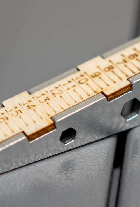
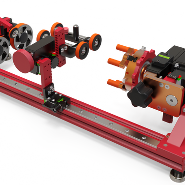
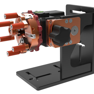
Grip a pen or an ice bucket with equal confidence. PiBurn delivers unmatched flexibility, pinpoint accuracy, and rapid setup—handling feather‑light pieces and hefty blanks without breaking a sweat.
Learn More ↗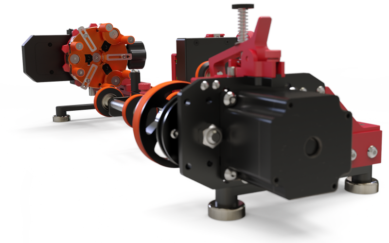
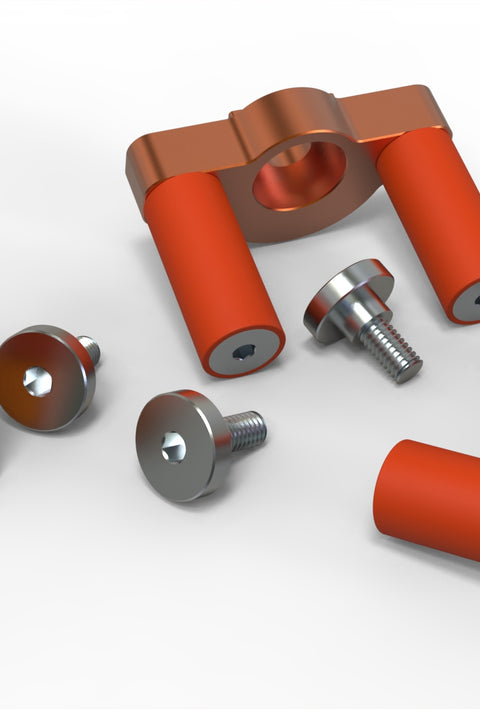
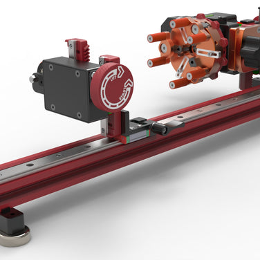
CNC‑machined from aluminum and stainless steel, then hand‑assembled to exacting tolerances, PiBurn thrives under constant use delivering unwavering precision and rock‑solid durability for every engraving challenge.
Learn More ↗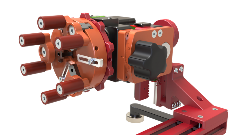
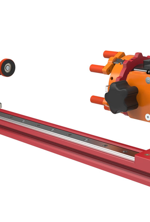
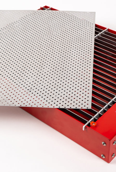
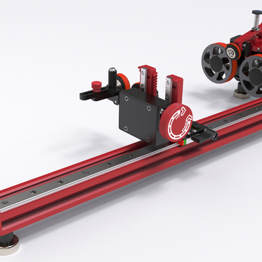
PiBurn clicks onto any laser bed in seconds with its powerful magnetic feet, no tools needed. The patented system lets you swap cups, mugs, or dog bowls in under 5 seconds, so you move from job to job at lightning speed.
Learn More ↗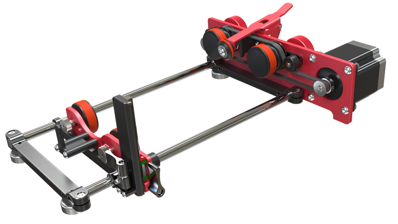
Upgrading to PiBurn isn’t just an investment. it’s a revenue driver. By slashing engraving time, eliminating errors, and expanding your product offerings, it typically pays for itself in a matter of weeks. Increase throughput, reduce per-piece labor, and boost your bottom line with every rotation.
Learn More ↗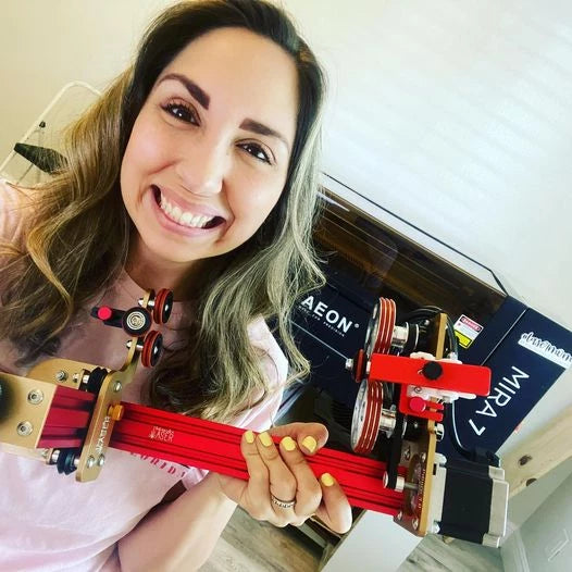
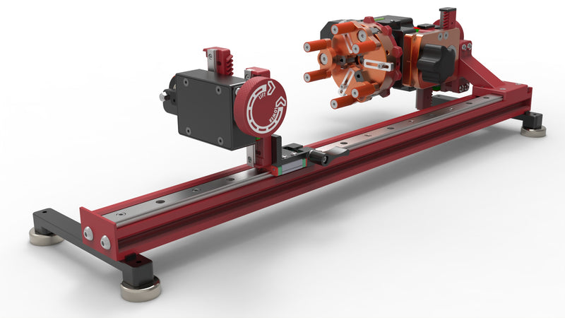
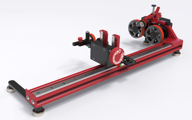
The Latest and Greatest Version of The World’s Best Laser Rotary Attachment
The PiBurn V is the ultimate roller rotary attachment for laser engraving, designed for both beginners and experienced users alike. The “easiest professional rotary in the world” is now even more simple to setup and use.
Shop PiBurn VTRAILBLAZERS, EDUCATORS, COMMUNITY BUILDERS, LEADERS, MAKERS AND INNOVATORS RELY ON PIBURN

“That Mom With A Laser, Inc. was born from a desire to give and help other women learn how to operate industrial laser engraving machines. I’m passionate about helping others turn their ideas into finished products and “owning their awesome” while they do it! For my tumblers, I turn to PiBurn, of course! Beyond just being a great rotary, there is a whole community and support structure built for the maker.”

“I ordered my PiBurn in March of 2022, I was looking for other rotary options. I love the ease of use of my PiBurn v4 and use it several times a week. The flexibility and the direction of LensDigital is very appealing to me. They have some very progressive additions coming up that will further the use of their rotary on many items that are difficult to manage in a roller style rotary.”
“I am selling around 100 custom-designed tumblers a month, and it has become the biggest sellers on my website. I can’t even say I have a favorite because each new one I design becomes my favorite. I don’t even know which I like better, creating the design or watching it come to fruition on a tumbler. The PiBurn Grip helps me engrave with confidence each time”

“I work locally with real estate agents and commercial businesses to make branded merchandise that sets them above the rest—what pushed me to make the purchase was having several local businesses asking for engraved wine glasses and tumblers. I knew I needed to go ahead and order the PiBurn, and all I can say is WOW! The rotary is very impressive; you can see and feel the quality when you take it out of the box.”