


LED MiniBoard prototype
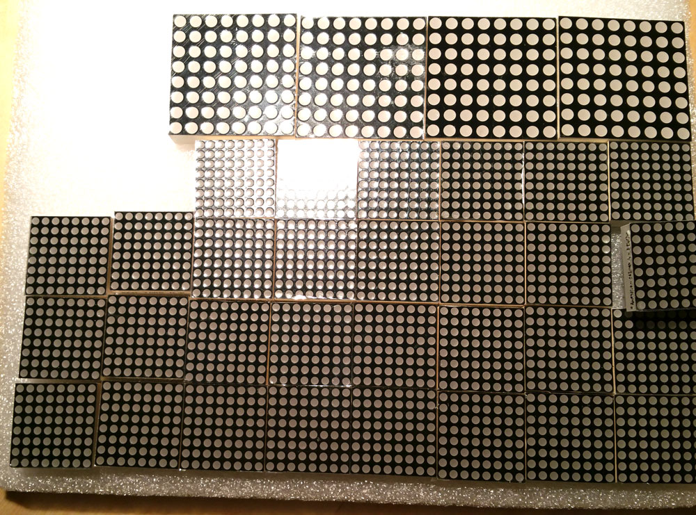
Recently I started working on a custom LED Matrix displays and I’m very excited that LED Matrices for new displays finally arrived last night!
I knew they will be small, but actually seeing them in front of my eyes still shocked me a little on how small they are! You can almost fit 4 of these in place of regular 8×8 matrix block!
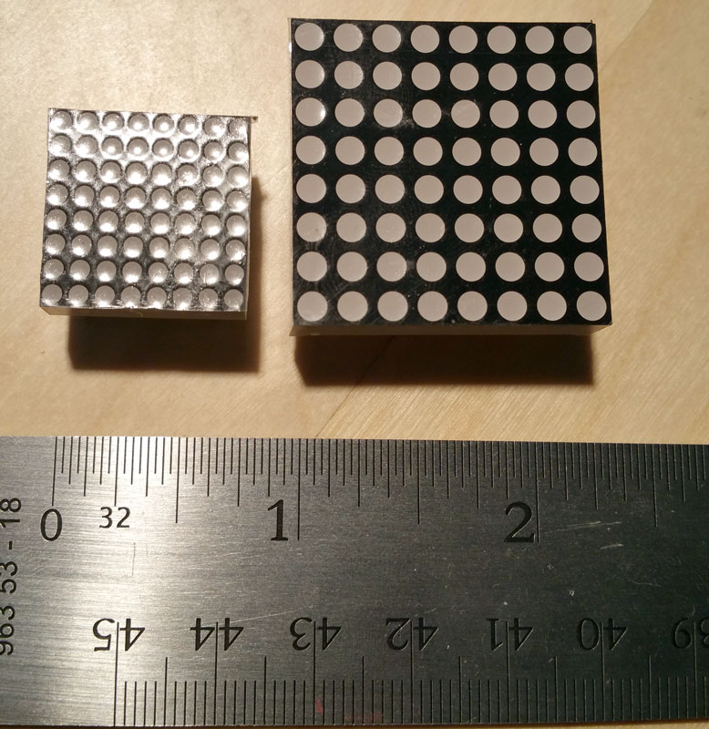
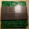
After a quick test, everything seems good, datasheets are accurate and pins are actually nicely organized. Left row red LEDs anodes, middle common cathodes, and right row are green LED anodes.
I ordered several varieties. Red LEDs are all the same, but when it comes to Green color there are some choices. There’s something that’s called Super Green and Pure Green. As name implies Pure Green is closer to wavelength of actual green color (512-525nm) while Super Green is closer to the yellow at 565-575nm. Catch is that Pure Green LEDs are almost double the price of Super Greens. Another difference is that Pure Greens are significantly brighter and have much higher forward voltage than other LEDs. This creates two issues. One is that driver ICs might not be able to handle higher load. Another is financial as cost of the LED matrices puts affordability of the displays at risk.
Fortunately after visual inspection, I happy to see that Super Greens are actually look very green to me, and I plan to use them in the displays going forward.
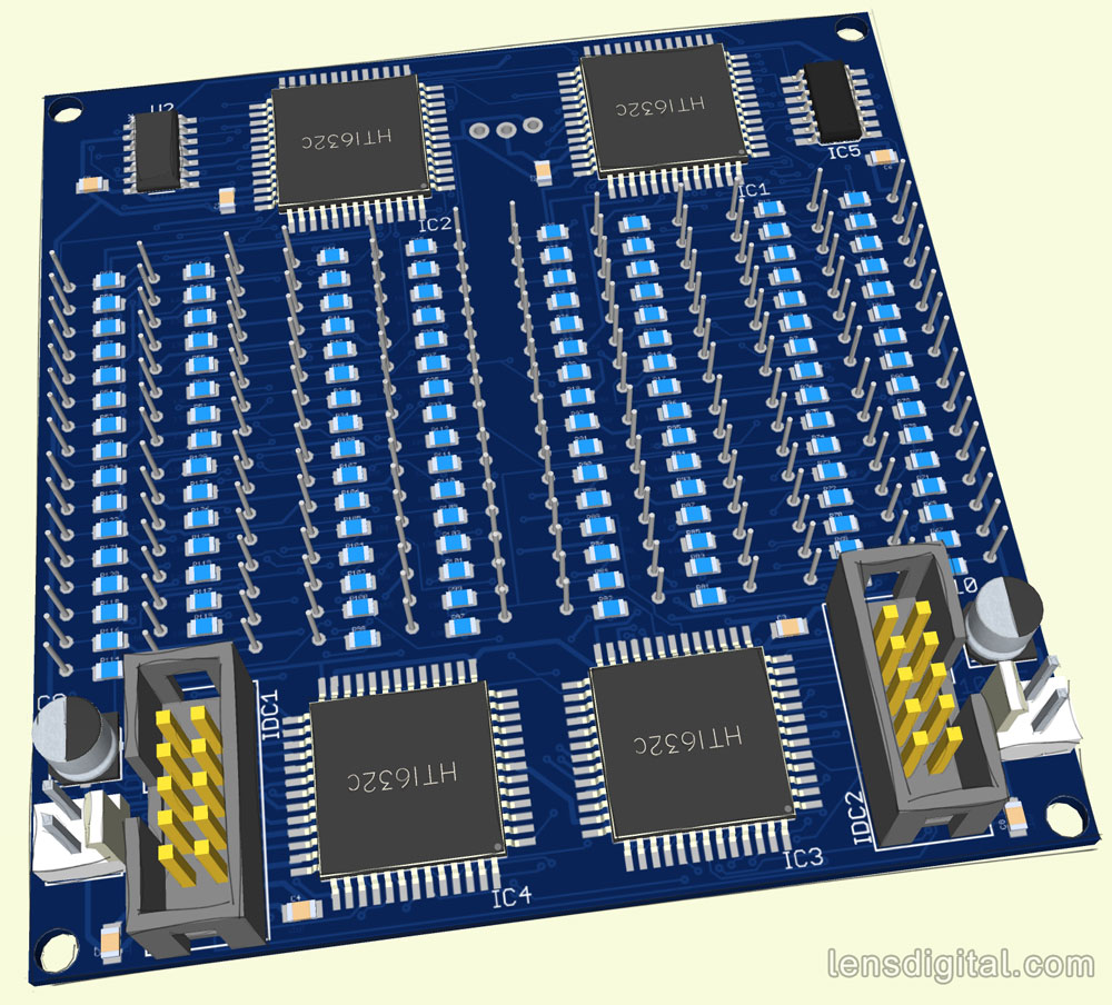
I’ve finalized first version of PCB and already sent it to manufacturer. Hopefully I’ll get it back in couple of weeks, and they it will be really “fun” to solder all these resistors 🙂


2 comments on “LED MiniBoard prototype”
florinc
Nice!
I would have expected a LED driver (such as HT1632) not to require current limiting external resistors. No other common cathode LED driver that I know does that.
Also, the LED matrix creators could have placed the pins around the edges, thus allowing for an IC (LED driver, that is) in the middle of the matrix and saving some board space.
I have 4 of these LED matrices myself, and it is hard to design something around them because of the pin distribution.
Any idea on the retail price? Is it going to be compatible (in functionality) with the old 32×16 displays from Sure?
Keep up the great job! Looking forward to the finished product.
bratan
Thanks!
Yeah figuring out good resistor value is a pain, I’ll have to do it thru trial and error to match luminosity. I looked at Sure’s displays and with resistors that they use (100 and 220 ohms) it actually exceeds SINK current spec of the HT1632c chip (32 LEDs can light up per COM theoretically). But hey it works 🙂
Pin density is a pain in the butt. I could’ve made these much shorter, but autorouter in Eagle just couldn’t handle it 🙁
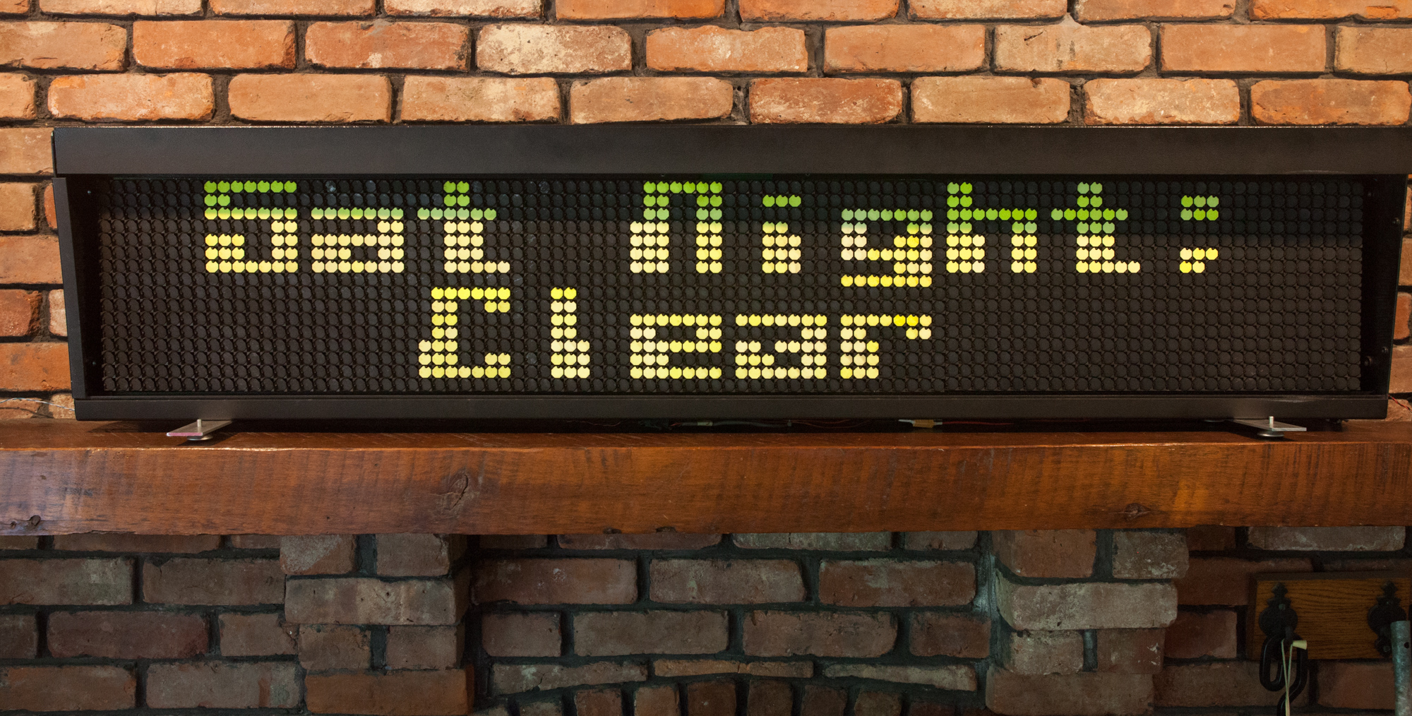
These displays should be compatible with Sure’s, maybe with exception of swapped colors (Red instead of Green) which is an easy fix in software. Pins unfortunately are not compatible (I decided to use 2×5 IDC), but it’s 5V all around.
I’m not sure about final price yet, but it will be slightly more than Sure’s. If I can source parts for cheap, it can be in under $40.